
HRI Expert Introduction#
What is HRI®#
HRI® stands for Hybrid Reactive Index. HRI® reflects the process in a value. An index that is created by combining three process parameters using a formula. This index enables a unitless representation of the process. HRI® reflects the hole process in a value.
What offers HRI®#
The HRI® process monitoring system provides comprehensive control over every step of the machining process. Separate limits can be defined for each process step, each axis and each sensor. By implementing the extended status, limit violations and error reactions are displayed in plain text on the HMI. A feed limiter allows precise process control. Component identifiers, such as data matrix codes, can also be recorded for efficient tracking.
What should be done with HRI®?#
The implementation of HRI aims to use only high-quality parts (no raw or bad parts) in assembly to ensure a trouble-free production process. The application also includes the early detection of tool breakages and the continuous monitoring of process and input quality. The implementation of preventive maintenance ensures that potential problems are proactively addressed and rectified.
Process monitoring HRI®#
With this process values is the HRI® calculated#
Synchro Fine:
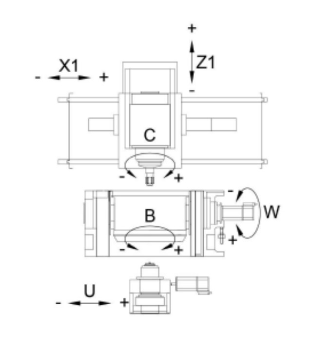
- Temperature from the B - axis und C - axis
- Current / forces from the B - axis, C - axis, X - axis and Z - axis
- Values from the vibration sensor B - axis, C - axis and U - axis
Synchro Form:
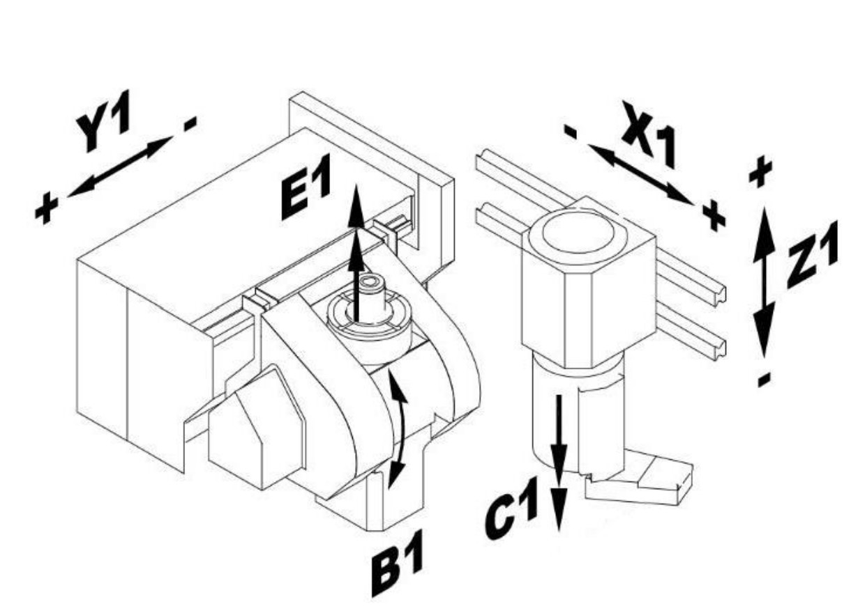
- Temperature from the C – axis und E – axis
- Current / forces from the C – axis and E – axis [X – axis, Y - axis (skiving) and Z – axis in process]
- Values from the vibration sensor C – axis and * E – axis.
HRI® values#
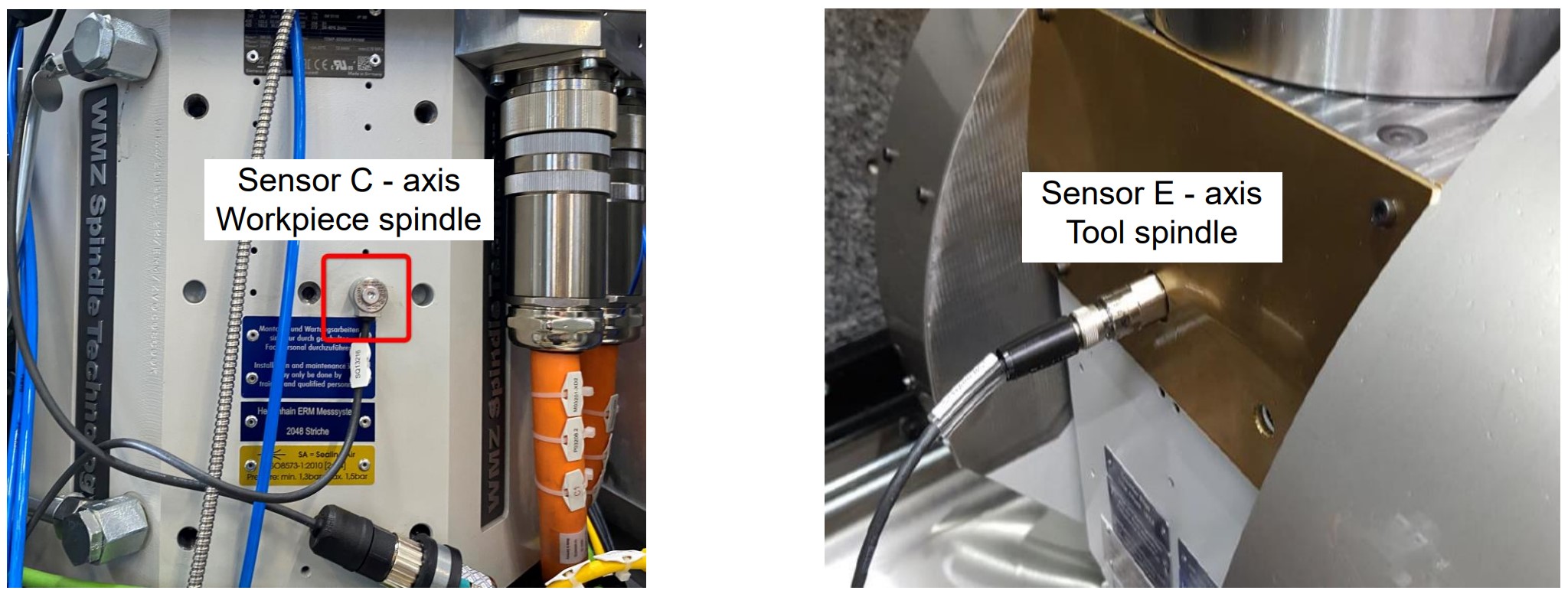
Temperature#
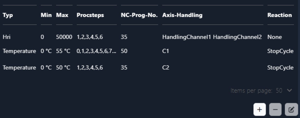
The temperature can be monitored. Changes in the temperatures of the tool spindle (B axis or E axis) and the workpiece spindle (C axis) have a negative effect on the quality of the workpieces. The higher temperatures cause a change in the length and height of the spindles. The temperature sensors are installed in the motors and the individual values are provided as parameters by the BOSCH Rexroth control or the Siemens control.
The temperature can be monitored individually. If the set value is exceeded, the corresponding error response is triggered. In the example, the machine is stopped with “StopCycle” if the limit value of 50°C or 55°C is exceeded.
Currents / forces#
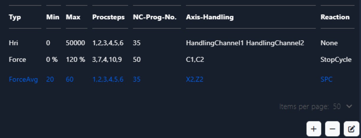
The current values are recorded from the axes that are involved in the process. These correspond to the process forces. The individual values are summed up squarely. In this way a better signal / noise ratio is achieved. The current values are provided as parameters by the BOSCH Rexroth control or the Siemens control. The values are percentages of the nominal current.
In addition to recording the individual forces, HRI also offers the option of monitoring the average value of these forces. This average value is calculated at the end of the machining process and enables monitoring of both a minimum and a maximum range. This monitoring is crucial in order to identify any deviations in force behavior during the process and to react at an early stage if necessary.
However, it is important to note that there is no direct contact between the workpiece and the tool at the start of the machining process. In this phase, monitoring for an absolute minimum value would not make sense, as this does not provide any meaningful information. The absolute minimum value at the beginning does not differ from the value that would occur after a tool breakage. It is therefore advisable to activate monitoring for an average value.
Currents / forces - Synchro Fine#
From the following axis are the forces measured at the Synchro Fine machines:
- B-axis (Tooling spindle)
- C-axis (Workpiece spindle)
- X-axis (infeed axis)
- Z-axis (oscillating axis)
It is possible that the motors may be briefly overloaded, e.g. during acceleration. With Bosch Rexroth controllers, measured values can exceed 100%. The spindles can be overloaded up to 350% and the linear axes up to 450%.
By machines with activated tailstock HRI® calculated an Offset from 30%. Because tailstock and Z-axis working against each other. The operation grade from machines with activated tailstock is about 30% higher than machines without tailstock. The offset is adjustable in the settings.
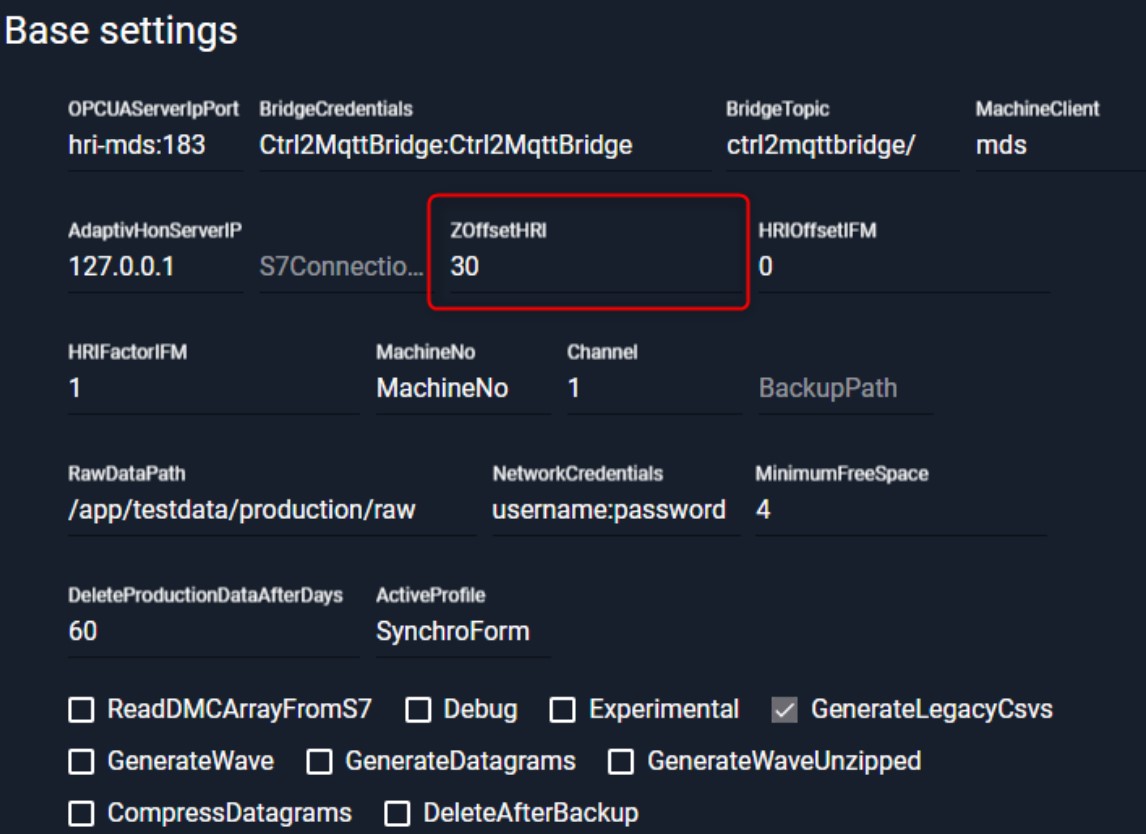
If there is no offset, the Z axis is weighted too heavily int the calculation of HRI and changes in the other axes are not recognized. When computing the Z-axis offset, results less than zero are not accepted and written to zero.
Example of normal condition for Synchro Fine: 𝐹𝐻𝑅𝐼 = 1.269,07 Example for shaft honing without offset for Synchro Fine: 𝐹𝐻𝑅𝐼 = 3.297,07
Currents / forces - Synchro Form#
From the following axis are the forces measured:
- E – axis (Tooling spindle)
- C – axis (Workpiece spindle)
- X – axis (infeed axis, in process)
- Z – axis (oscillating axis, in process)
- Y – axis (infeed axis – only skiving, in process)
The motors can be briefly overloaded, particularly during acceleration processes. It is important to emphasize that the Siemens controllers do not record any measured values that exceed 100% of the nominal current. No measured values above 100% are transmitted to HRI. When setting limit values, it must be ensured that no values above 100% are entered for machines with a Siemens controller. HRI would not trigger an error response for limits above 100% of the nominal current.
Vibration sensors#
Sensors and evaluation units from the manufacturer IFM are installed to detect vibrations in the machine. Präwema install three different vibration sensors from IFM. On the one hand single axis vibration sensors (VSA001 or VSA004) are installed as standard. The picture shows an IFM VSA001.
On the other side, IFM has been manufacturing a triaxial vibration sensor since 2022 (VSM10X). This is installed on the tooling spindle of the Synchroform or on special request on the tooling spindle of the Synchrofine.
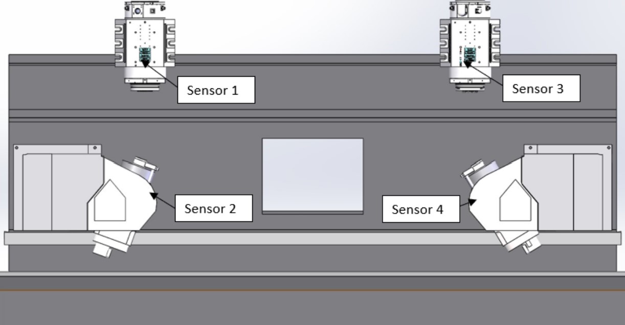
Vibration sensors Synchrofine#
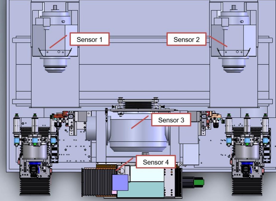
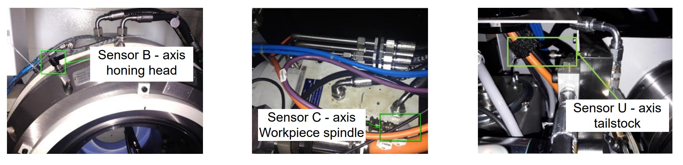
The vibration monitoring sensors are mounted on the following axles on external honing machines:
- B-axis (tooling spindle - sensor 3) Y-direction
- C-axis (workpiece spindle - sensors 1+2) Y-direction
- U-axis (tailstock - sensor 4) X-direction
Vibration sensors SynchroForm#
The vibration monitoring sensors are mounted on the following axles on external honing machines:
- E-axis (tooling spindle - sensor 2+4)
- C-axis (workpiece spindle - sensors 1+3) A three-axis vibration sensor was installed on the workpiece spindle.
Vibration sensors#
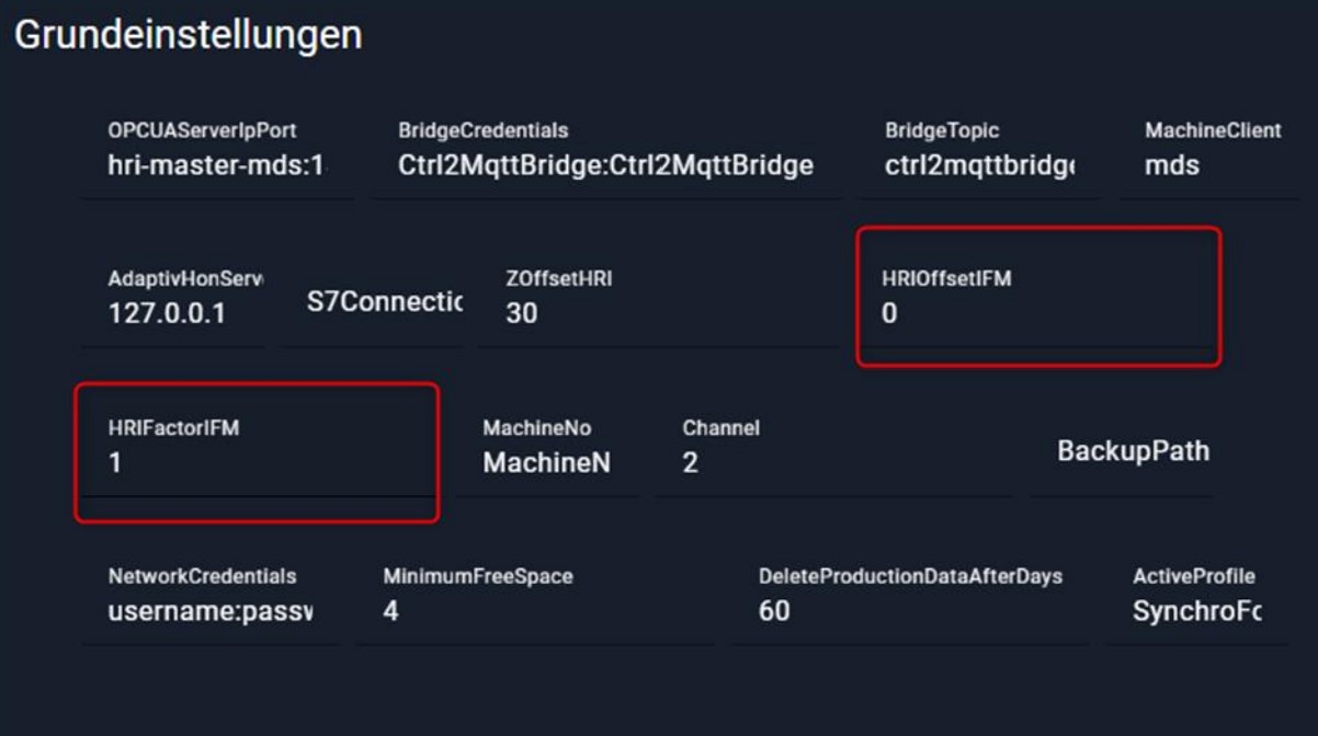
The data recorded by the individual vibration sensors is transmitted as raw data, with each sensor outputting its measured value in mg (thousandths of the acceleration due to gravity). In order to emphasize the importance of the measured vibration values in the calculation of the HRI, specific adjustments have been implemented. These include an adjustable offset and factor, which are available in the basic settings. These adjustments make it possible to influence the proportion of vibration in the calculation of HRI and adapt it to specific requirements.
The default offset is 0 and the factor is 1.
The formula is: 𝑉𝐼𝐵𝐻𝑅𝐼 = 𝐼𝐹𝑀 − 0 ∗ 1
HRI® visualization#
HRI® monitoring object#
An HRI® monitoring object should always be created. On the one hand, to set the scaling of the Y-axis in the diagram. On the other hand, because otherwise the secondary processes will also be recorded and the result of the HRI® calculation will be distorted. Due to the acceleration of the linear drives in the delivery processes, an HRI® value that is too high is calculated.
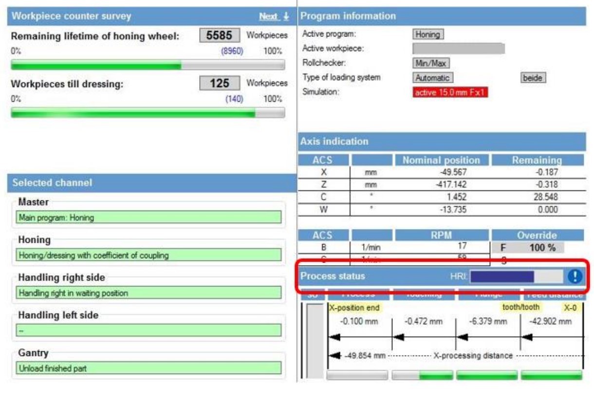
Honing HMI#
The current HRI® value is displayed as a bar graph in the “Operate" window. The value is scaled to 110% of the maximum HRI® value. If the set value is exceeded, the color changes from blue to red. Currently, this function is only active for the Synchrofine.
Overview of limit values#
The programs present in the file system of the Honing HMI are loaded. The current program is preselected. Individual variables can be monitored, and error responses defined under diagnostic objects
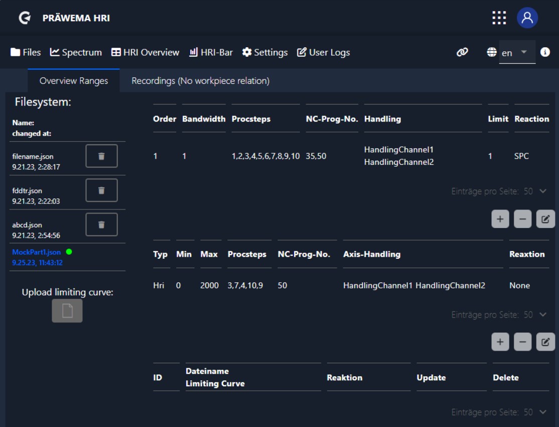
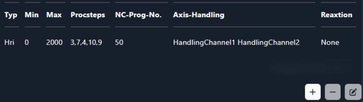
Edit Screen#
An editing screen has been added since version 2.5. The limits are easier to set with the screen and the possibility of incorrect entries has been minimized. When HRI® is selected, only HandlingChannel 1 or HandlingChannel 2 can be selected.
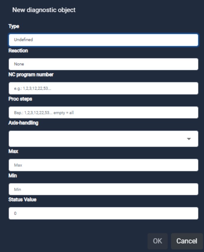
HRI® monitoring object#
| designation | description |
|---|---|
| Type | The variables can be selected here |
| Reaction | Error reaction that is triggered, when the value is exceeded or not reached |
| NC program number | NC program to be monitored |
| Proc steps | Process steps to be monitored |
| Axis – handling | Axis or handling to be monitored |
| Max | Maximum value that must not be exceeded in the process step |
| Min | Minimum limit that must be reached in the process. Only possible with HRIAvg, HRI Integral and ForceAvg |
NC program number#
The table lists various NC program numbers that represent different subroutines. Each number represents a specific subroutine that performs a specific machining task, such as honing, profiling or calibrating.
| NC Program number | |
|---|---|
| 1 | Footprint / KM 0 measurment |
| 2-9 | Other programs (turning, drilling, etc.) |
| 21 | Honring measuring head |
| 22 | Honring measuring gear |
| 31 | Profiling head |
| 32 | Profiling gear |
| 33 | Pre profiling only with VSD |
| 34 | Profiling only with VSD |
| 35 | Skiving |
| 40 | Omit workpiece measurement |
| 41 | Workpiece measure left |
| 42 | Workpiece measure right |
| 50 | Honing |
| 51 | Dressing gearing with DDG |
| 52 | Dressing tip circle |
| 53 | Dressing with VSD |
| 60 | Calibrate |
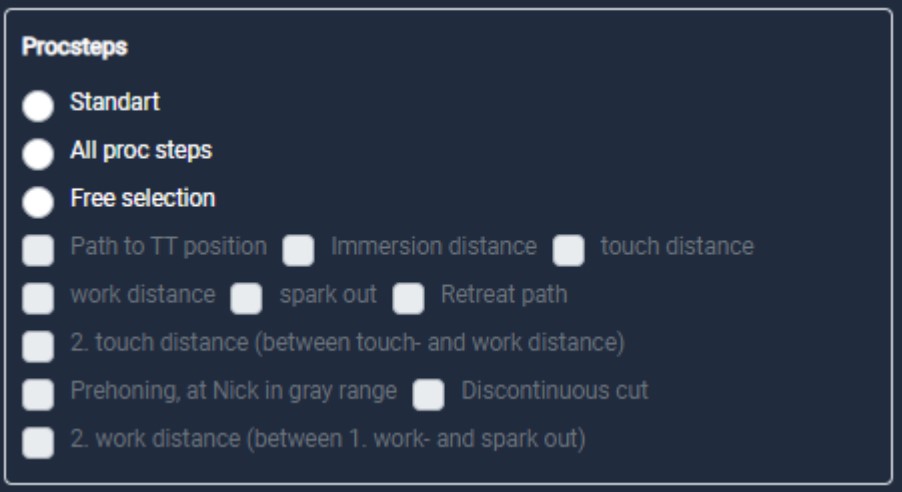
Honing machines – Proc steps#
During honing, various program steps are carried out. Each of these steps, such as: touch distance, immersion distance and working distance, represents a specific process within the honing process.
| Process steps honing | |
|---|---|
| 0 | Inactive |
| 1 | Way from 0 to tooth-tooth position (rapid) |
| 2 | Immersion distance (high feed of 100 mm/min) |
| 8 | Prehoning, at Nick in gray range |
| 3 | Touching (1) |
| 7 | Touching (2) (optional) |
| 9 | Lift distance (optional) |
| 4 | Working (1) |
| 10 | Working (2) (optional) |
| 5 | Spark out (residence time on end distance with oscillation) |
| Process steps dressing with VSD | |
|---|---|
| 25 | VSD cuts without correction |
| 26 | VSD cuts with correction |
Skiving machine and other machines DVS Technology Group#
With the gear skiving machine, each skiving stroke is considered a separate process step. If, for example, a workpiece is to be processed with 15 peeling strokes, the machine records 15 process steps accordingly. With other machines from the DVS Technology Group, the process steps are individually adapted to the processing of the machine.
Error reaction#
The following is a description of the error reactions that are triggered when certain values are exceeded or not reached. These error reactions could include various actions such as stopping the process, triggering an alarm or displaying a warning message to indicate deviations or problems in the machining process.
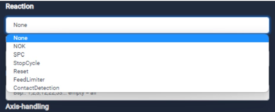
Error reaction#
| Error reaction | |
|---|---|
| None | No reaction from the Machine |
| NOK | The part is discharged as NOK part |
| SPC | The part is discharged as SPC part |
| StopCycle | The machine will stop after the cycle |
| Reset | Imidiate stop and retraction to X0 position |
| Feed Limiter | Feed limitation from the infeed axis |
| Contact Detection | Contact detection from the tooling to the workpiece |
Error reaction Min#
If the average value of the honing process is not reached, the monitoring responds and the defined error reaction is executed. The minimum monitoring is intended to detect a honring break. If there is little or no contact between the honring and the workpiece, this is detected, and the error reaction is triggered. Only possible for HRIavg, HRIsurface and ForceAvg.
Error reaction Max#
If the entered value in the process is exceeded, the monitoring responds and the defined error reaction is executed. If there are too high forces, vibration or temperatures during the honing process, the error reaction is triggered.
HRI® overview#
The HRI® diagrams and the HRI® table are summarized in the HRI® overview. Here is an example of a test machine at Präwema. The HRI limit has been set at 5,000 HRI points. Accordingly, a red line has been drawn in the chart at 5,000. The y-axis of the chart has been scaled 6,000 (+ 20%). For machines where the process can run in parallel, a distinction is made between the left and right sides of the machine.
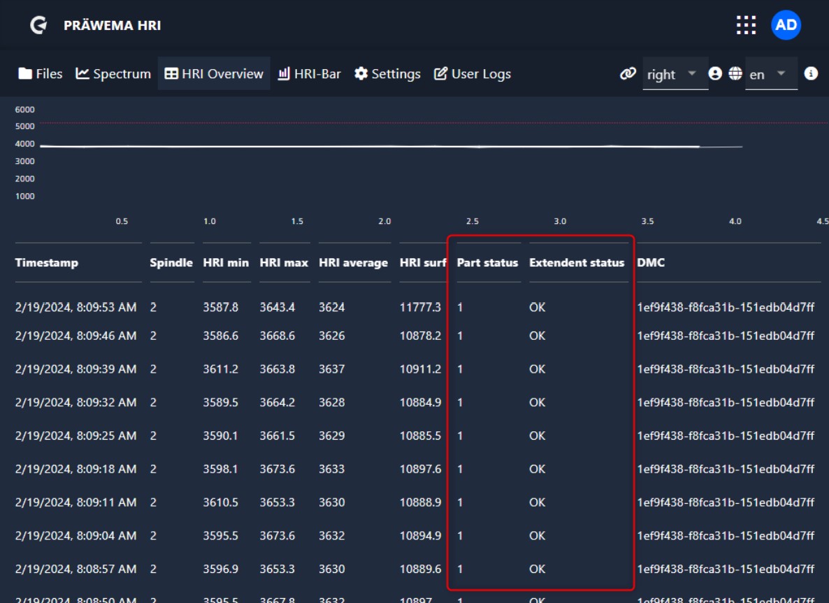
| Workpiece status | |
|---|---|
| 1 | Measurement is OK - limit value was not exceeded |
| 2 | The limit was exceeded during processing |
| 4 | The average value was not reached during processing |
| 8 | The integral was not reached during processing |
| 16 | Error message via HRI® (vibration, force or temperature) |
| 32 | Error message via HRIexpert® (order object or limiting curve) |
| 64 | Stop after the end of cycle |
| 128 | Eject workpiece (SPC) |
| 256 | Reset - Emergency retraction to X0 position |
| 512 | Eject workpiece (NOK) |
Workpiece status#
The individual workpiece status signals are bit values and can be combined with one another. A triggering error message “4 - The average value was not reached during processing” with the error response “64 - Stop after end of cycle” would be output as workpiece status “68”.
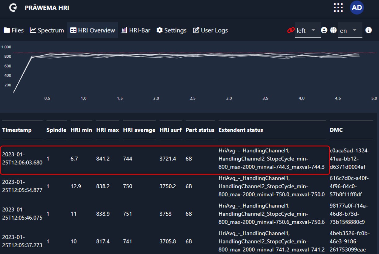
Extended status#
In the extended status, the limit violations are displayed as plain text. With the set limit values and the values of exceeding or falling below the values, as well as the set error reaction.
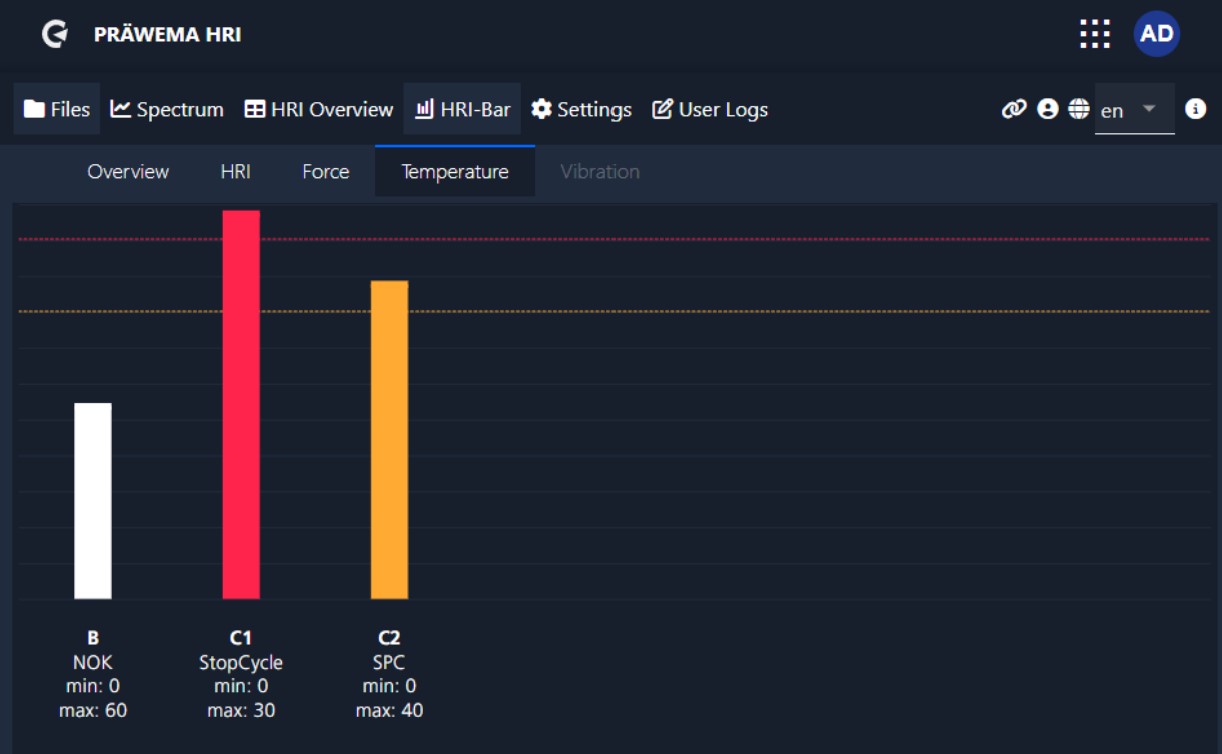
HRI - Bar#
As of version 3.1 an overview page has been added. All 4 variables that can be monitored are shown here. If a monitoring object is created, the corresponding button is activated. If the value is below 80% of the limit value, the button is displayed as a white circle with a check mark. If the value is more than 80% of the set limit value, the button will turn orange and if it is exceeded, it will turn red.

Click on the button to switch to the single view. Here the created monitoring objects are displayed. The monitoring objects of HRIAvg, HRIsurface and ForceAvg are not displayed. The values of these monitoring objects are calculated only at the end of the process.
In the example, three monitoring objects have been created for the temperature. At the C1 spindle the limit value is exceeded, at the C2 spindle the measured value is between 80% and 99%. At the B spindle the measured temperature value is below 80% of the limit value.
Feed Limiter#
How does the feed limiter work#
The machine feed rate is reduced by entering limit values for current and vibrations. If 100% of the set limit value is exceeded, the feed limitation becomes active. First, the feed is only reduced. If 120% of the limit exceeded, the feed limiter writes the value to 0%. The feed rate is increased again only when the value falls below 100% of the limit.
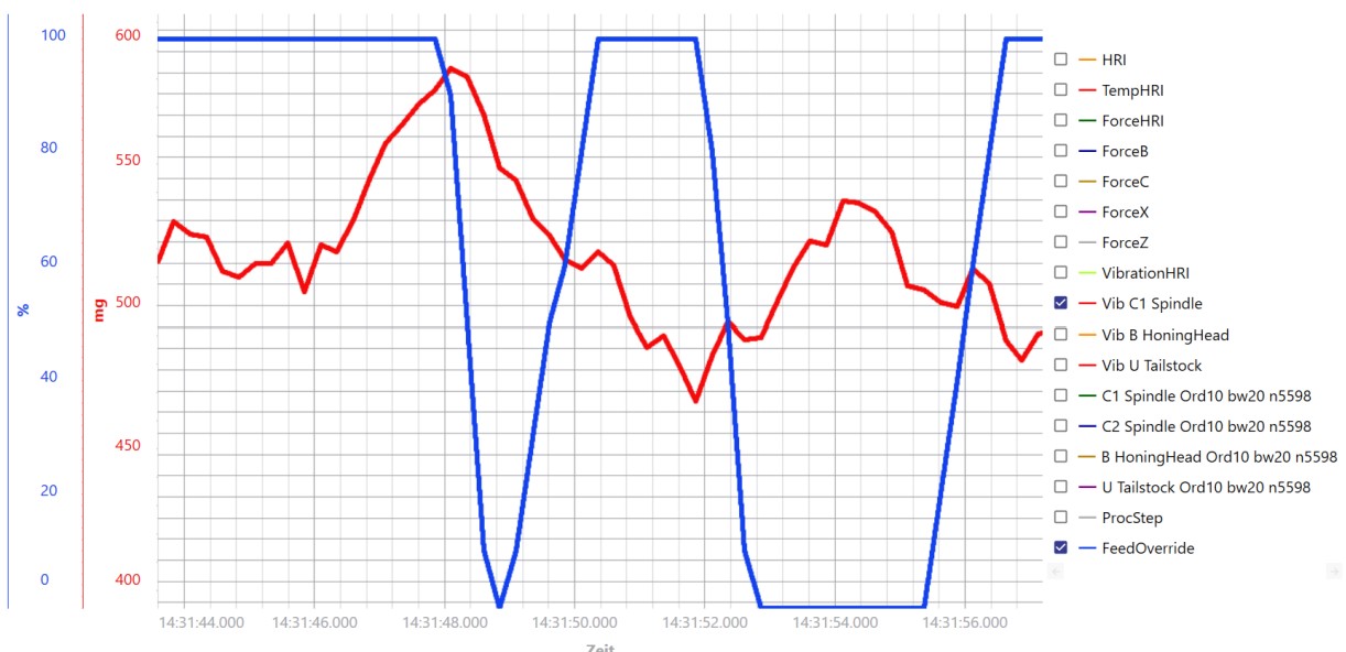
Example of a feed limitation#
The machine feed is limited by the vibrations of the U-axis. First the feed is reduced to 90% and after this measure is insufficient it is reduced to 0%. When the vibrations fall below the limit value again, the feed is increased again.
HRI® settings#
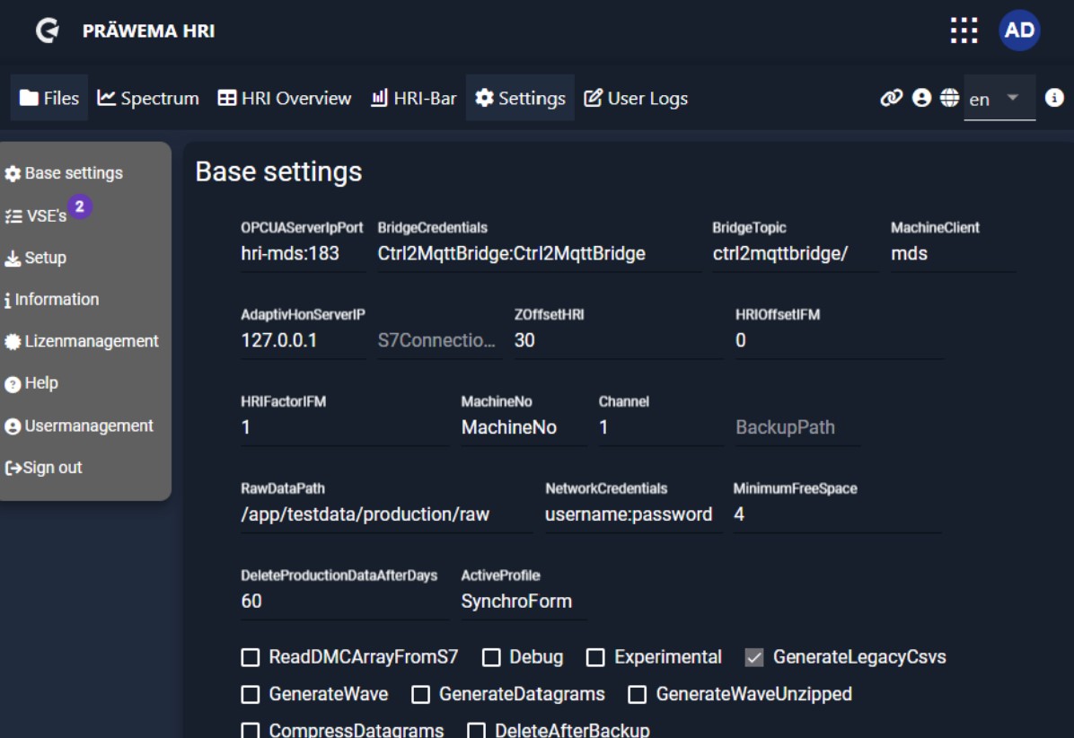
Base settings#
All important settings for communication between the HRImachine and the control can be set under base settings. Furthermore, some additional options can be set. The basic settings are defined once during commissioning. No further adjustments are required. Except in the event of faults or changes to the programming, no changes need to be made here.
Basic settings for Praewema installation#
| Settings | |
|---|---|
| OPCUAServer Port | IP address of the controller with the OPC UA server port |
| Bridge Credentials | Username and password for the network bridge for DVS Edge |
| Bridge Topic | For DVS Edge |
| Machine Client | For DVS Edge |
| Adaptiv Hon ServerIP | IP address of the controller with the AdaptivHonServer |
| S7Connection IP | IP address of the S7 CPU in Profinet |
| ReadDMC ArrayFromS7 | Read data matrix code from Siemens S7 |
| Channel | NC Channel from the Siemens S7 controller |
| PublishRaw DataViaMqtt | Sends raw data via MQTT |
| ForceOrder Monitoring | At least one regulatory monitoring system must be in place. |
| Experimental | Beta functions – be careful with production machines! |
| ActiveProfile | Active profile – SynchroForm or SynchroFine |
| InvertHRI CommMonitor | Invert communication monitoring. |
| FeedOverrideInPercent | Feed limiter is written to PLC in percent. |
Basic settings for costumer#
| Settings | |
|---|---|
| ZOffsetHRI | Only for SynchroFine – offset to the force of the Z axis when the tailstock is activated |
| HRIOffsetIFM | Offset from the vibration of the HRI calculation |
| HRIFactorIFM | Factor from the vibration of the HRI calculation |
| MachineNo | Number of the machine |
| Debug | Debug function for more recordings |
| BackupPath | Storage path for the HRI backup on a server |
| RawDataPath | Storage path for the raw data |
| Network Credentials | Username and password to log in to a server |
| Minimum Free Space | Minimum free disk space (in MB) |
| Delete Production Data After Days | Deletion of logging files after number of days on the machine. |
| LegacyCsv SaveAvgMax | Stores the average and maximum amplitude of the vibrations for IO components. |
| DeleteAfter Backup | Deletes the logging files on the machine if an external backup path is set up. |
Base settings for data formats#
| Settings | |
|---|---|
| Generate LegacyCsvs | Create standard CSV log files |
| Generate Wave | Creates a compressed WAVE file from the data from the vibration sensors. |
| Generate Datagrams | Generates datagrams for analyzing the parts |
| Generate WaveUnzipped | Creates an uncompressed WAVE file from the data from the vibration sensors |
| CompressData grams | Compress datagrams |
| EnableRaw Data | Record raw data |
VSE base settings#
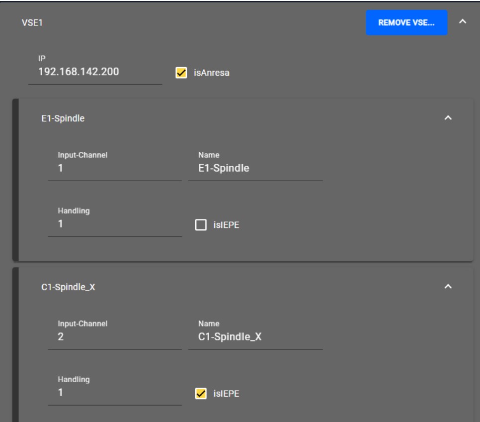
The individual VSE evaluation units from the manufacturer IFM are displayed in the VSE basic settings. Usually, one or two VSE with the firmware AnReSa are used. 4 vibration sensor inputs can be connected to each evaluation unit. On older machines, a VSE unit was installed for each sensor. In the example, a single-axis VSA001 sensor and a three-axis VSM103 sensor are connected. The single-axis sensor VSA001 is connected to sensor input 1 and set up as an IFM standard vibration sensor. The three-axis sensor is connected to inputs 2-4 and set up as an IEPE sensor (current). Each axis of the sensor requires a separate input on the evaluation unit.
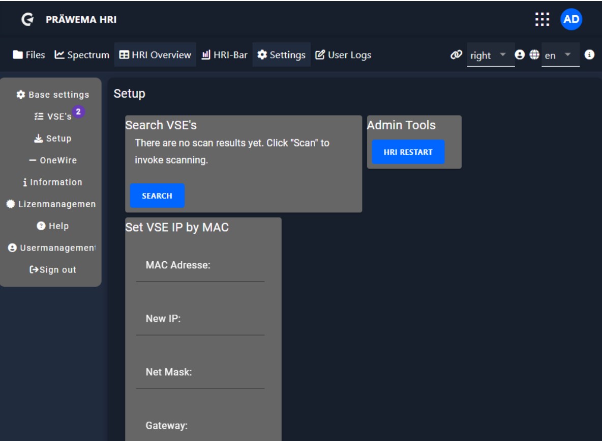
Setup#
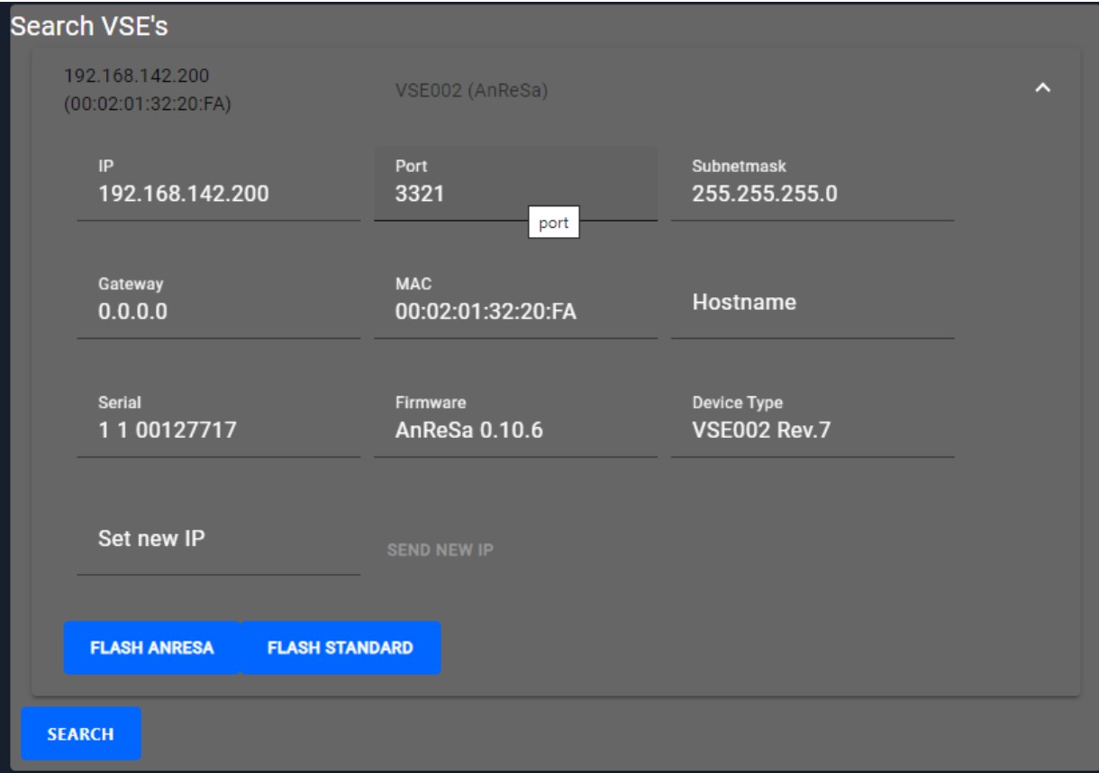
In the “Setup" tab, you can search for the evaluation units of the VSE vibration sensors. The HRI backend can be restarted and if the search for a VSE was unsuccessful, the IP address of the VSE unit can be changed via the MAC address.
After identifying a VSE unit, all relevant settings and information are displayed. In this context, it is possible to change the IP address. It is also possible to switch between the two firmware versions (AnReSa or Standard). Please note that changes with the IFM Octavis software can only be made with the standard firmware. Flashing the AnReSa firmware is only possible from hardware version (DeviceType) 6. If the hardware is older, updating the firmware requires the VSE unit to be replaced.
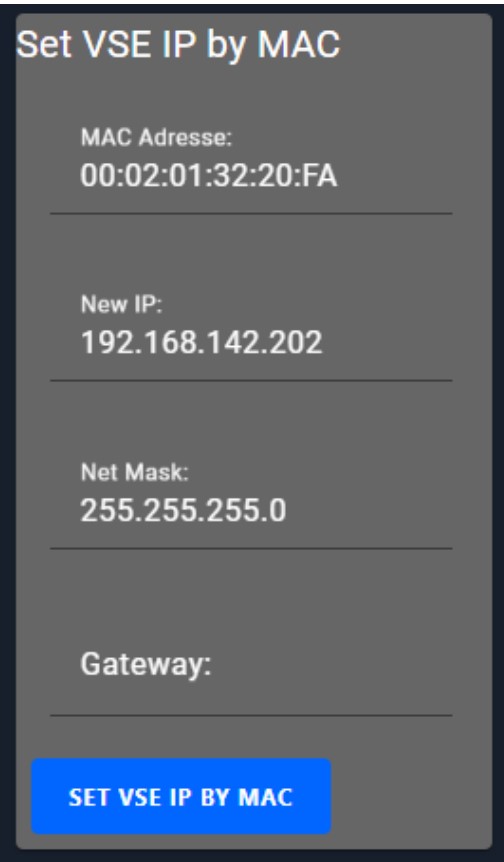
If no VSE unit is found or it is not possible to configure the IP address, there is the option of setting the IP address using the MAC address. The MAC address is located on a sticker on the side of the VSE unit.
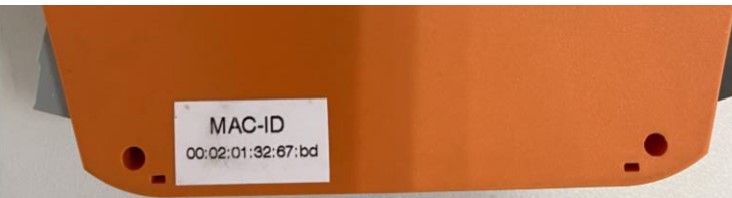
To carry out the configuration, the MAC address, the new IP address and the subnet mask must be entered.
To apply changes, it is necessary to restart HRI. HRI can be restarted in the setup tab or with the task manager.
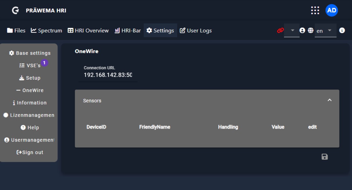
OneWire#
The tooling and workpiece spindles have temperature sensors to monitor the bearing temperature. These sensors use the OneWire bus. The IP address of the controller must be entered in the HRI. After a successful connection to the controller, all connected sensors are automatically recognized. The sensors are assigned to the respective mounting locations by using the serial number of the OneWire sensors
Information#
The backend and frontend versions are displayed under Information. In case of errors, be sure to indicate the program versions.
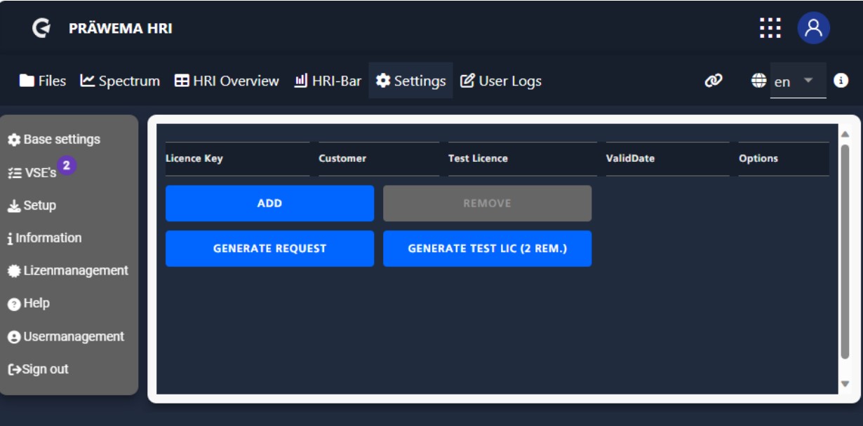
License management#
The installed licenses are displayed under the license management. Under the button “ADD” further licenses can be installed and under “REMOVE” the licenses can be deleted again. With “GENERATE TEST LIC” a test license can be generated twice. The test license works until the last day of the following month.
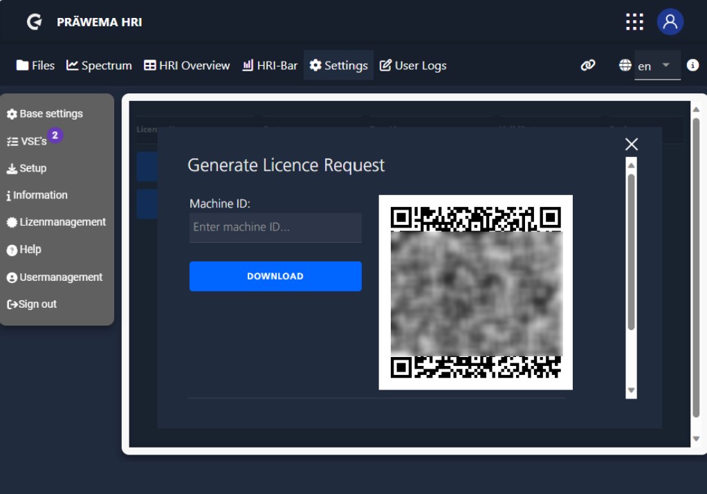
GENERATE REQUEST" creates an LRQ file. This file can then be used to generate a permanent license. The machine number must be entered to create the LRQ file. The license key is linked to a MAC address of the controller. When the controller is replaced, a new license must be created. Test licenses can be used for the transition. The LRQ file is saved in the Downloads folder.
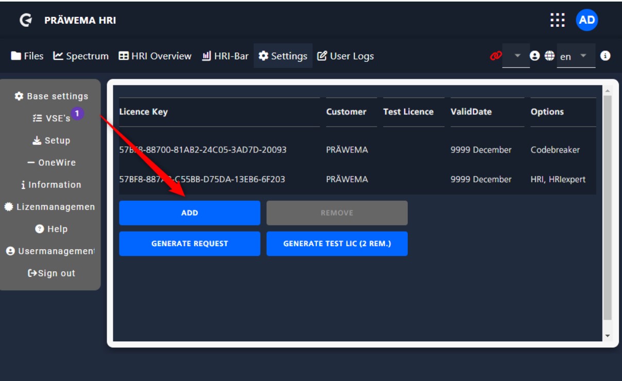
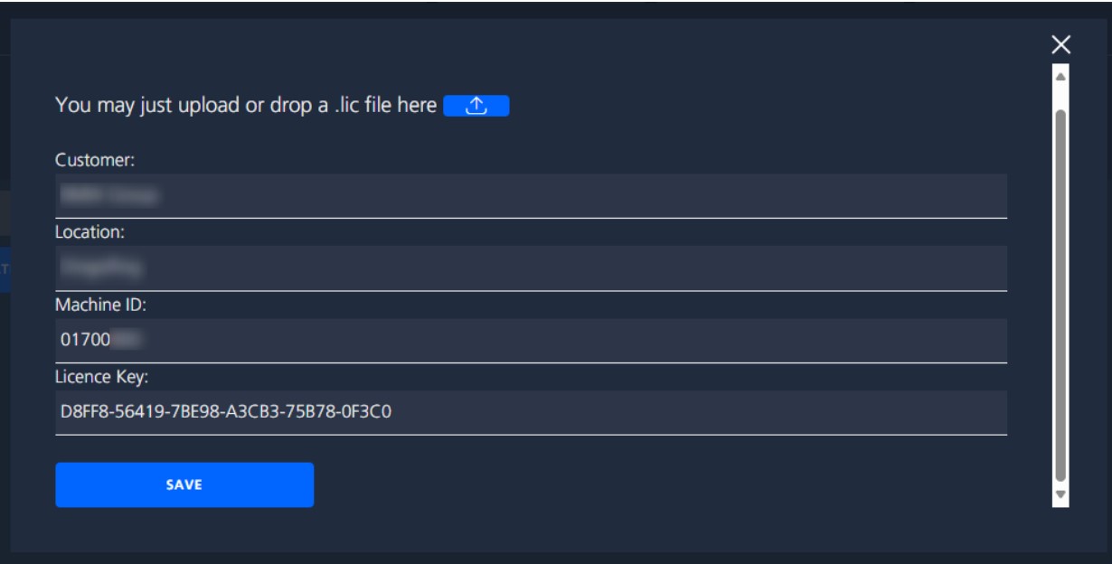
The information from the License Request File can be used to create a permanent or provisional license and a License File is generated. This license file must be installed in the HRI in order to activate all functions. The ADD button opens another window.
Here you can import the LIC file by clicking on the blue button.
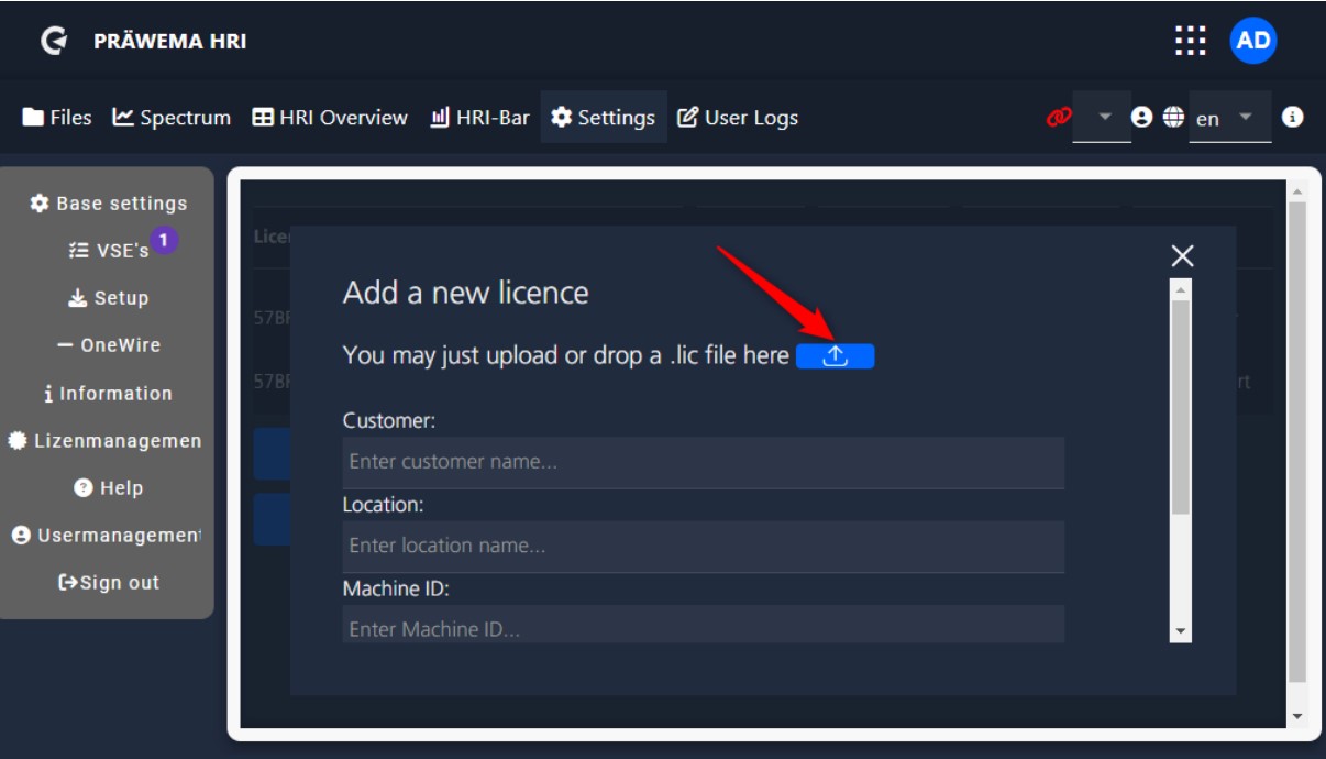
After the import you have to scroll down in the window and save the license key. The new license key is then displayed in the overview.
User management#
Different users can be created in user management. There are 3 permission levels
| Permission levels | |
|---|---|
| Operator | No authorization to change limit values. |
| Setter | Changes to the limit values by the setter are possible |
| Administrator | Changes to limit values and settings are possible. |
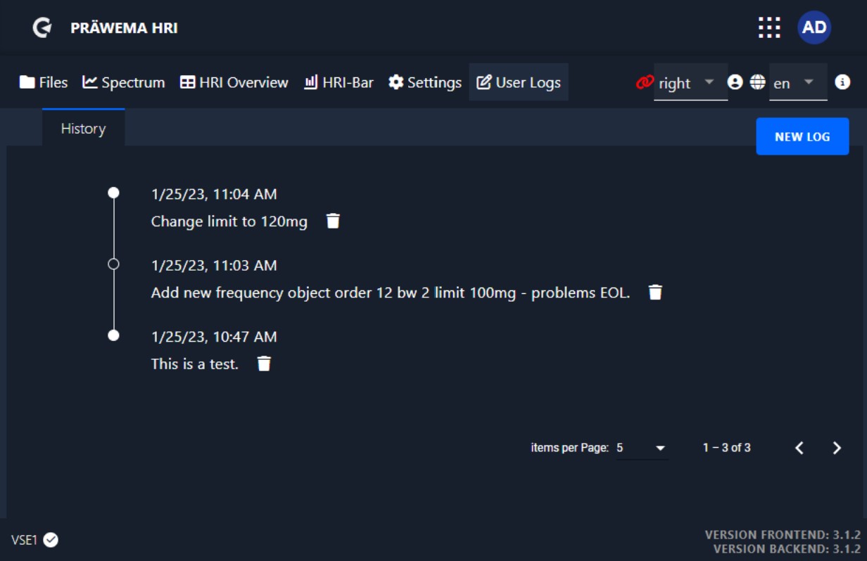
User logs#
A logbook for the machine can be created in the “User Logs” tab. Here notes about changes and adjustments can be entered. This allows you to document why HRI objects were changed and what effects it has.
Conclusion#
Thank you for taking the time to read through the first part of my comprehensive manual on HRI Expert. I hope that you have gained a deeper understanding of the system and its capabilities.
As I conclude this first part, I want to let you know that there is more to come. In the next part of my manual, we will dive deeper into the advanced features and applications of HRI Expert. We will explore topics such as:
- Order analysis
- Limiting curve
- Recording in Spectrum
- FeedLimiter
Stay tuned for the next part of my manual, where we will continue to explore the capabilities and applications of HRI Expert. If you have any questions or feedback, please don’t hesitate to reach out to me. I am always here to help.